EN
EN


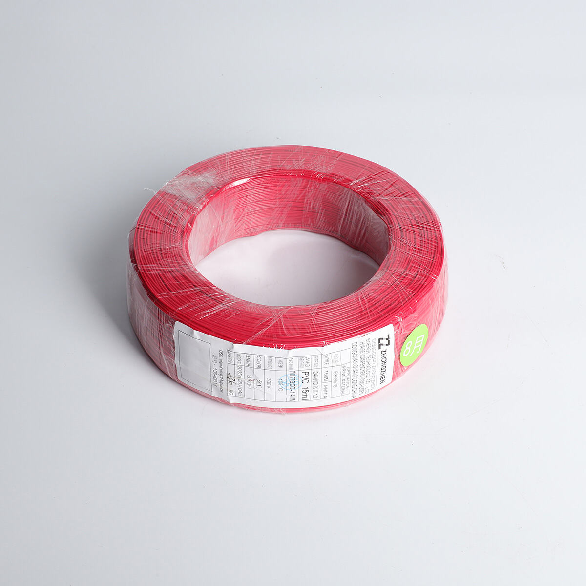
Modern electrical systems depend entirely on the quality and reliability of their foundational components, with electric wire cable serving as the critical pathway for power transmission across residential, commercial, and industrial applications. The performance of any electrical installation directly correlates to the specifications, materials, and construction quality of the cables used throughout the system. Understanding how electric wire cable functions within power delivery systems reveals the engineering principles that ensure consistent electrical flow, safety standards, and long-term operational reliability. Professional electricians and engineers recognize that proper cable selection forms the backbone of efficient power distribution networks.
Fundamental Components of Electric Wire Cable Systems
Conductor Materials and Their Impact on Performance
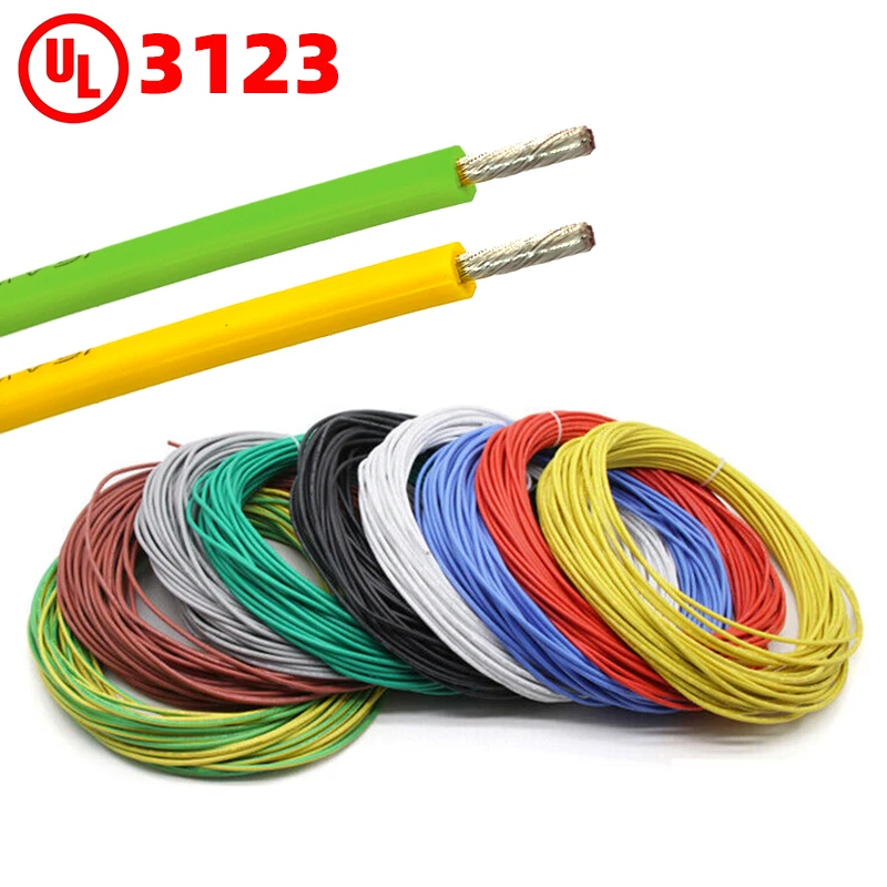
The conductor material represents the most critical element in electric wire cable design, directly affecting electrical conductivity, resistance levels, and overall power transmission efficiency. Copper conductors remain the industry standard due to their exceptional electrical properties, offering low resistance and high current-carrying capacity across various temperature ranges. Tinned copper conductors provide enhanced corrosion resistance, particularly valuable in marine environments or applications exposed to moisture and chemical contaminants. The conductor gauge, measured in American Wire Gauge (AWG) standards, determines the current-carrying capacity and voltage drop characteristics of the cable system.
Silver-plated copper conductors offer superior performance in high-frequency applications, though their cost limits usage to specialized electronic and telecommunications equipment. Aluminum conductors present a cost-effective alternative for large-scale power distribution, though they require careful consideration of expansion coefficients and connection techniques. The stranding configuration of conductors affects flexibility, with fine-stranded designs providing better bend radius capabilities for applications requiring frequent movement or installation in tight spaces.
Insulation Materials and Electrical Safety
Insulation materials surrounding the conductor prevent electrical leakage while protecting against environmental hazards, with different polymer compositions suited to specific operating conditions and performance requirements. Silicone rubber insulation excels in extreme temperature applications, maintaining flexibility and dielectric properties across temperature ranges from -65°C to +200°C. Cross-linked polyethylene (XLPE) insulation provides excellent electrical characteristics with superior resistance to chemical degradation and moisture absorption.
Polyvinyl chloride (PVC) insulation offers cost-effective protection for general-purpose applications, though temperature limitations restrict its use in high-heat environments. Thermoplastic elastomer (TPE) compounds combine the processing advantages of thermoplastics with the performance characteristics of thermoset rubbers. The insulation thickness directly impacts the cable's voltage rating, with industry standards specifying minimum wall thicknesses based on intended operating voltages and safety margins.
Power Transmission Principles in Cable Systems
Current Flow and Resistance Management
Electric wire cable facilitates power delivery through controlled current flow, where the conductor's cross-sectional area and material properties determine resistance characteristics and heat generation during operation. Ohm's law governs the relationship between voltage, current, and resistance, with cable designers optimizing conductor dimensions to minimize power losses while maintaining cost-effectiveness. Skin effect becomes significant at higher frequencies, where current density concentrates near the conductor surface, potentially requiring specialized stranding techniques or conductor configurations.
Temperature coefficient of resistance affects conductor performance as operating temperatures fluctuate, with copper exhibiting predictable resistance increases as temperatures rise above ambient conditions. Cable ampacity ratings account for heat dissipation capabilities, considering installation methods, ambient temperatures, and grouping factors that influence thermal performance. Proper load calculations ensure that electric wire cable operates within safe temperature limits throughout its service life.
Voltage Drop Considerations and System Efficiency
Voltage drop represents the reduction in electrical potential that occurs as current flows through cable resistance, with excessive drops leading to equipment malfunction, reduced efficiency, and potential safety hazards. The National Electrical Code establishes voltage drop guidelines, typically limiting drops to 3% for branch circuits and 5% for combined feeders and branch circuits. Cable length significantly impacts voltage drop calculations, with longer runs requiring larger conductor sizes to maintain acceptable voltage levels at load terminals.
Power factor considerations become crucial in alternating current systems, where reactive components can increase current flow without corresponding increases in useful power delivery. Cable manufacturers provide voltage drop tables and calculation formulas to assist engineers in selecting appropriate conductor sizes for specific applications. Computer modeling software now enables precise voltage drop analysis for complex distribution systems, accounting for load diversity, harmonic content, and dynamic operating conditions.
Environmental Factors Affecting Cable Performance
Temperature Effects on Electrical Properties
Operating temperature significantly influences the electrical and mechanical properties of electric wire cable, with both conductor resistance and insulation performance varying across temperature ranges. High temperatures accelerate insulation aging processes, potentially leading to premature failure if cables operate consistently above their rated temperature limits. Thermal cycling creates mechanical stress on cable components, particularly at interfaces between different materials with varying expansion coefficients.
Cold temperature applications require special consideration for insulation flexibility, with standard PVC compounds becoming brittle at sub-zero temperatures while specialized cold-weather formulations maintain flexibility. Heat dissipation capabilities depend on installation methods, with cables installed in conduit or cable trays requiring derating factors to account for reduced cooling. Thermal modeling helps predict cable temperatures under various load conditions, enabling proper sizing and installation practices.
Moisture and Chemical Resistance
Moisture infiltration represents a primary threat to cable integrity, causing insulation degradation, conductor corrosion, and potential electrical failures that compromise system reliability. Water-resistant cable designs incorporate specialized jacket materials and sealing techniques to prevent moisture penetration during normal operating conditions. Underground and direct burial applications require enhanced moisture barriers, often including aluminum or copper tape shields beneath the outer jacket.
Chemical exposure varies by installation environment, with industrial facilities presenting challenges from acids, bases, oils, and solvents that can attack standard cable materials. Chemical-resistant formulations utilize specialized polymer compounds engineered to withstand specific chemical exposures while maintaining electrical performance. Regular inspection protocols help identify early signs of chemical attack or moisture intrusion, enabling preventive maintenance before failures occur.
Installation Practices for Optimal Performance
Proper Routing and Support Methods
Cable installation techniques directly impact long-term performance and reliability, with proper routing practices preventing mechanical stress, excessive bending, and damage during installation procedures. Minimum bend radius specifications protect cable integrity, with violations potentially causing conductor breakage, insulation cracking, or internal component displacement. Cable support systems must accommodate thermal expansion and contraction while preventing excessive sag or tension in horizontal runs.
Conduit and raceway systems provide physical protection while facilitating organized cable management, though fill ratios must comply with electrical codes to ensure adequate heat dissipation. Cable tray installations offer accessibility for maintenance while supporting large cable quantities, requiring proper spacing and support intervals based on cable weights and spans. Pulling tensions during installation must remain within manufacturer specifications to avoid damaging conductor strands or insulation systems.
Connection Techniques and Termination Quality
Proper termination techniques ensure reliable electrical connections while preventing hot spots, voltage drops, and premature failures at cable endpoints and splice locations. Terminal selection must match conductor materials and sizes, with compression fittings providing superior reliability compared to mechanical screw-type connections. Conductor preparation involves proper stripping techniques that avoid nicking or cutting individual strands, maintaining full current-carrying capacity.
Splice enclosures protect connection points from environmental exposure while maintaining electrical integrity throughout the cable system service life. Heat-shrink tubing and tape applications provide additional insulation and environmental protection at termination points. Quality control procedures during installation help identify potential connection problems before energizing the electrical system, reducing the likelihood of field failures and safety incidents.
Testing and Quality Assurance Methods
Electrical Testing Procedures
Comprehensive testing protocols verify electric wire cable performance characteristics and ensure compliance with applicable electrical codes and safety standards. Insulation resistance testing measures the integrity of cable insulation systems, identifying potential weak points or contamination that could lead to electrical faults. High-potential (hipot) testing applies controlled overvoltage conditions to verify insulation strength and identify manufacturing defects or installation damage.
Continuity testing confirms proper conductor connections throughout cable runs, identifying opens, shorts, or crossed connections that could affect system operation. Time domain reflectometry (TDR) enables precise fault location in installed cables, facilitating efficient troubleshooting and repair procedures. Thermal imaging surveys identify hot spots and overloaded conditions during system operation, enabling preventive maintenance actions before failures occur.
Manufacturing Quality Standards
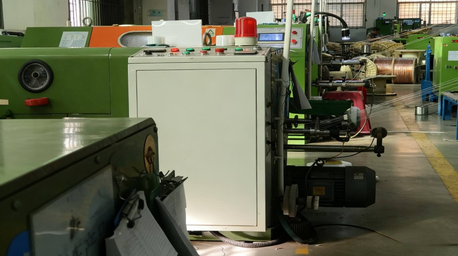
Cable manufacturing processes incorporate multiple quality control checkpoints to ensure consistent product performance and compliance with industry standards such as UL, CSA, and IEC specifications. Raw material testing verifies conductor purity, insulation properties, and jacket characteristics before production begins. In-process monitoring controls conductor dimensions, insulation thickness, and overall cable geometry throughout the manufacturing process.
Final product testing includes electrical property verification, mechanical strength evaluation, and environmental resistance confirmation before cables receive certification markings. Statistical process control methods track manufacturing variations and identify trends that could affect product quality. Third-party testing laboratories provide independent verification of cable performance claims and regulatory compliance, ensuring customer confidence in product specifications.
FAQ
What factors determine the current-carrying capacity of electric wire cable?
Current-carrying capacity depends on conductor cross-sectional area, material properties, insulation temperature rating, installation method, ambient temperature, and cable grouping factors. Larger conductor sizes provide higher ampacity ratings, while installation in conduit or bundled configurations requires derating factors. Temperature limitations of insulation materials establish maximum safe operating currents, and proper load calculations must account for continuous versus intermittent loading conditions.
How does cable length affect voltage drop in electrical systems?
Voltage drop increases proportionally with cable length due to conductor resistance, requiring larger wire sizes for longer runs to maintain acceptable voltage levels at load terminals. The relationship follows Ohm's law, where voltage drop equals current multiplied by resistance, and resistance increases with cable length. National Electrical Code guidelines limit voltage drops to ensure proper equipment operation and system efficiency, typically requiring voltage drop calculations for circuits exceeding specified lengths.
What environmental conditions require special cable considerations?
Extreme temperatures, moisture exposure, chemical contact, UV radiation, and mechanical stress require specialized cable designs and installation methods. High-temperature environments need cables with enhanced insulation materials like silicone rubber or XLPE, while cold conditions require flexible compounds that maintain properties at low temperatures. Wet locations demand water-resistant designs with appropriate jacket materials and sealing methods, and chemically aggressive environments need specialized polymer formulations.
How often should installed cable systems undergo inspection and testing?
Inspection frequency depends on installation environment, system criticality, and applicable codes or standards, with annual visual inspections recommended for most commercial and industrial installations. Thermal imaging surveys should occur annually or when loading conditions change significantly, while insulation resistance testing may be required every three to five years or following environmental exposure events. Critical systems like hospitals, data centers, and emergency services may require more frequent testing to ensure continuous reliability and safety compliance.